Data Logging
The Data logging utility helps you collect sensor datasets from the sensor boards with the firmware that outputs sensor data through a COM port. This section describes how to set up and collect the sensor dataset.
This utility can help program the corresponding firmware binary with a data logging function to some NXP demo boards. For other boards, implement and program the firmware beforehand using the following specific data format.
Data Format Specification:
All characters are encoded in ASCII.
Data samples are separated by a single delimiter of space, comma, tab, or semicolon.
Every line of the dataset ends with ‘\r\n’ and contains N(N>=1)*channels of samples.
To capture data from the target board connected to the PC, navigate to the Data Logging utility page.
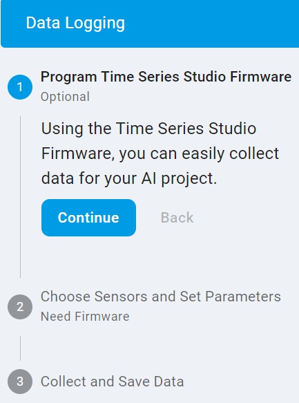
As shown above, the data logging process consists of three high-level steps.
The first step supports to program the firmware binary provided by the utility to the target board. The supported boards are listed in the
Target Boarddrop-down list. If the board is unsupported or has been programmed, the step can be skipped.The second step supports to get and set the sensor parameters from/to the board that has the functions after connecting to the COM port. This step is only relevant for the boards with firmware programmed in the first step. It can be skipped without the functions or requirements.
The third step supports to collect and save the sensor data from the target board after connecting the required COM port. It is necessary for any board for data logging.
Program Firmware (optional)
Make sure that the USB port for programming on the target board is connected to the PC first.

Click the
Refreshbutton.Select the
Debug Probe.Select the connected target board in the support list of the
Target Board.Click the
Programbutton to program the corresponding firmware binary.
Configure Parameters (optional)
Make sure that the corresponding USB port on the target board is connected to the PC first. This port is usually the same one used for programming.
Serial settings and Connect:

Click the
Refreshbutton.Select your target board COM port. For example, COM14.
Select the baud rate as supported in the list. The default is 115200.
Click the
Connectbutton and complete the board connection.
Parameter configuration:
After successfully connecting to the COM port in the second step, the utility retrieves system information automatically. The information includes the supported sensors, the default active sensor, and its parameters for the target board. A sensor becomes the active sensor when its tab is selected. For example, clicking the Temperature+Accel tab activates both the temperature and accelerometer sensors. To configure the parameters for one sensor, select the parameters from the value list and click the Config Data Logger button.
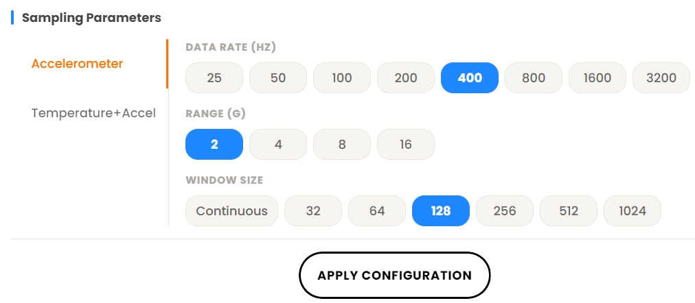
Note: The data collection in the third step is based on the last selected sensor with the configured parameters before leaving this step.
Serial Settings for Data collection
It is supported in the third step.
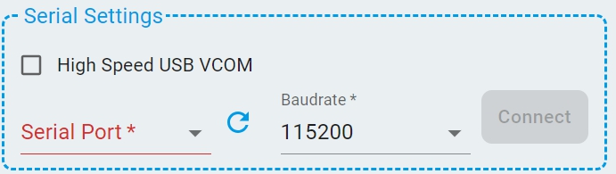
This serial port is identical to the one presented in the second step. Its settings and connection status are retained from the second step. It can be set and connected here if the second step is skipped. The serial port supports the low-speed COM port connection for data collection.
Check the High Speed USB VCOM if the High-Speed USB VCOM is supported and enabled on the target board for data collection.
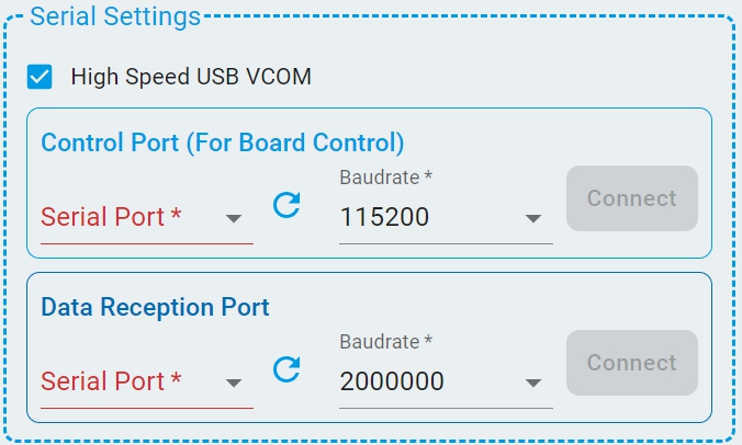
Then the Data Reception Port is added for the High-Speed USB VCOM settings and connection.
When the target board is selected from the support list of the Target Board in the first step and the value continuous is configured for continuous data collection in the second step, the system will first automatically detect whether the High-Speed USB VCOM is enabled on the target board.
Check the High Speed USB VCOM automatically if it is enabled.
Once checked, the Control Port is used for command communication and the Data Reception Port is used for continuous data collection.
Note: Make sure both ports on the target board are connected to the PC before setting.
Dataset Settings
The settings are required before collecting data in the third step.
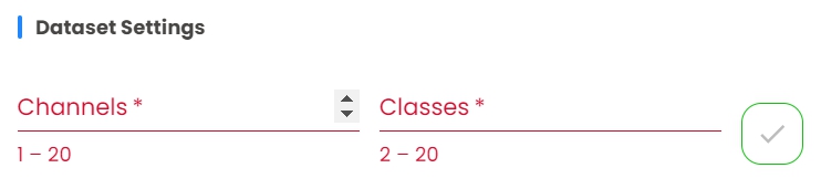
Specify the number of classes and number of channels of the dataset depending on your application. Confirm settings by clicking the √ button on the right.
Collect Dataset:
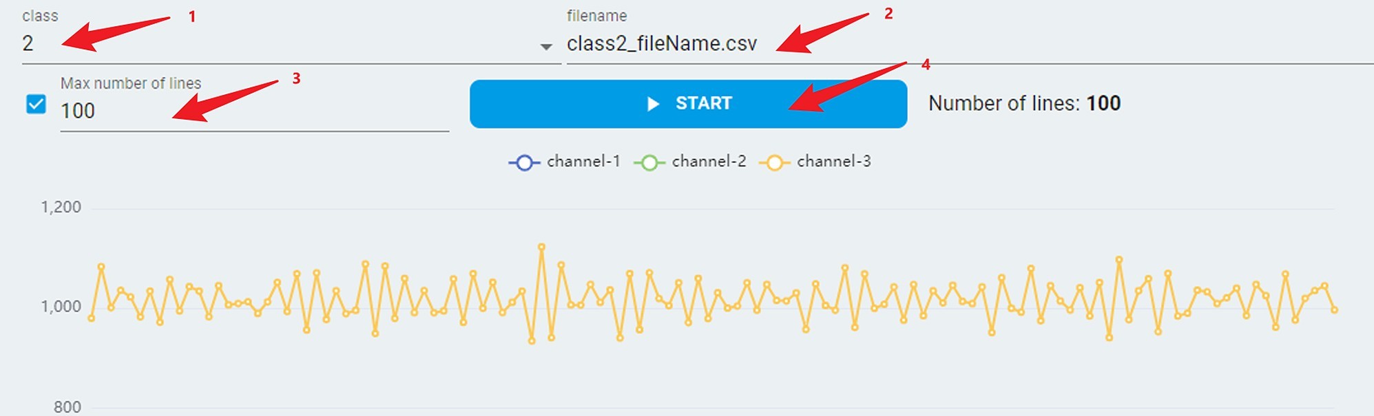
Select a target class for the dataset to be collected.
Customize a filename for the file to be saved.
Check the
max number of linescheckbox and specify the desired sample line count. Alternatively, use the default value of 100 lines.Click the
STARTbutton, the real stream data appears and auto saves in the file with maximum lines. However, for boards not in theTarget Boardsupport list, ensure that the board is already sending sensor data.To collect all datasets by selecting different target classes, repeat the above four steps.
To open the folder with the saved dataset file, click the Open Saved Dataset button.