TSS AFCI MCXN547 Project
Introduction
This document provides guidance for configuring and running the TSS AFCI embedded application on the MCXN547 platform. The project supports arc fault detection, multi-channel data acquisition, and flexible deployment modes.
System Overview
The application is a configurable embedded solution designed for:
Real-time arc fault detection (AFCI)
High-speed data acquisition
Multi-channel signal processing
It supports multiple operating modes and allows flexible integration with machine learning models generated by Time Series Studio (TSS).
Development Environment Setup
IDE Installation
Download the official MCUXpresso IDE from the NXP website: https://www.nxp.com/design/software/development-software/mcuxpresso-software-and-tools-/mcuxpresso-integrated-development-environment-ide:MCUXpresso-IDE?tab=Design_Tools_Tab
Project Import
Open MCUXpresso IDE.
Go to Quickstart Panel → Import project(s) from file system.
Select the provided project package (.zip).
SDK Installation
Download the MCXN547 SDK from the MCUXpresso SDK Builder.
Install the SDK into the IDE before building the project.
Application Configuration
Operation Modes
The application supports three execution modes controlled by the SW1 setting:
Mode |
Description |
|---|---|
0 or 3 |
Prediction Mode – Executes real-time inference on input data streams. |
1 |
Data Logging Mode – Captures raw data for offline analysis and model training. |
2 |
Data Logging Mode with Auto-Labeling – Captures data with automated label generation for supervised learning. |
Channel Configuration
The number of active ADC channels is controlled via the DEVICE_QUANTITY macro.
#define DEVICE_QUANTITY 4 // Range: 1–8, adjust based on hardware configuration
Channel Mapping
The following table illustrates the relationship between DEVICE_QUANTITY and the enabled ADC channels:
DEVICE_QUANTITY |
Active ADC Channels |
|---|---|
1 |
AFCI_CH1 |
2 |
AFCI_CH1, AFCI_CH2 |
3 |
AFCI_CH1, AFCI_CH2, AFCI_CH3 |
4 |
AFCI_CH1, AFCI_CH2, AFCI_CH3, AFCI_CH4 |
5 |
AFCI_CH1, AFCI_CH2, AFCI_CH3, AFCI_CH4, AFCI_CH5 |
6 |
AFCI_CH1, AFCI_CH2, AFCI_CH3, AFCI_CH4, AFCI_CH5, AFCI_CH6 |
7 |
AFCI_CH1, AFCI_CH2, AFCI_CH3, AFCI_CH4, AFCI_CH5, AFCI_CH6, AFCI_CH7 |
8 |
AFCI_CH1, AFCI_CH2, AFCI_CH3, AFCI_CH4, AFCI_CH5, AFCI_CH6, AFCI_CH7, AFCI_CH8 |
Benefits:
Dynamic channel selection for flexible I/O configuration
Scalable architecture supporting 1–8 channels
Optimized resource utilization based on hardware requirements
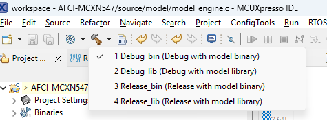
Build Configuration
The project supports two build configurations optimized for different development and deployment scenarios:
Option A: Development with Algorithm Library
This configuration links the device application with the algorithm library into a single executable binary.
Advantages:
Enhanced debugging capabilities with full application access
Improved MCU cache efficiency through unified memory layout
Reduced memory footprint for resource-constrained embedded systems
Single firmware image
Use Cases:
Active algorithm development and optimization
System-level debugging and profiling
Performance tuning and cache optimization
Option B: Development with Algorithm Binary
This configuration utilizes a pre-compiled algorithm binary, maintaining separation between the application and algorithm components.
Advantages:
Modular architecture enabling independent updates
Algorithm updates without a full application rebuild
Reduced compilation time during application development
Simplified version management for algorithm components
Enhanced IP protection for proprietary algorithms
Use Cases:
Production deployments with stable algorithms
Field updates requiring only algorithm modifications
Multi-team development with separate responsibilities
Configuration Selection:
In MCUXPresso IDE:
Right-click on the project in the Project Explorer.
Navigate to Build Configurations → Set Active.
Select your preferred configuration.
Memory Configuration (Optional)
Users can reallocate the SRAM memory depending on their application requirements. By default, the SRAM memory assignment is shown below. The BINARY_DATA region is used for the data memory of the algorithm binary generated from Time Series Studio.

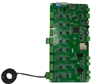
Hardware Setup
Connect the SWD interface (J6) on the target board to the PC using an external debugger (e.g., J-Link debugger).
Connect the target board to the PC via the USB port labeled
FSUSB, which supports both power supply and serial communication for basic logging and prediction results display. Connect the USB port labeledHSUSBto send sensor data from the board to the PC when using the data logging or auto-labeling function inTime Series Studio.Set up the AFCI test system and connect the current sensor to the target board.
Firmware and Model Deployment
Firmware Deployment
Program the firmware onto the target board.
Algorithm Deployment
Library deployment: Update the library file in the
./source/modeldirectory. Rebuild the project and flash the firmware onto the target board.Binary deployment: Program the algorithm model binary generated from Time Series Studio onto the target board using Time Series Studio or another flash tool. The flash address for programming is
0x100000by default.
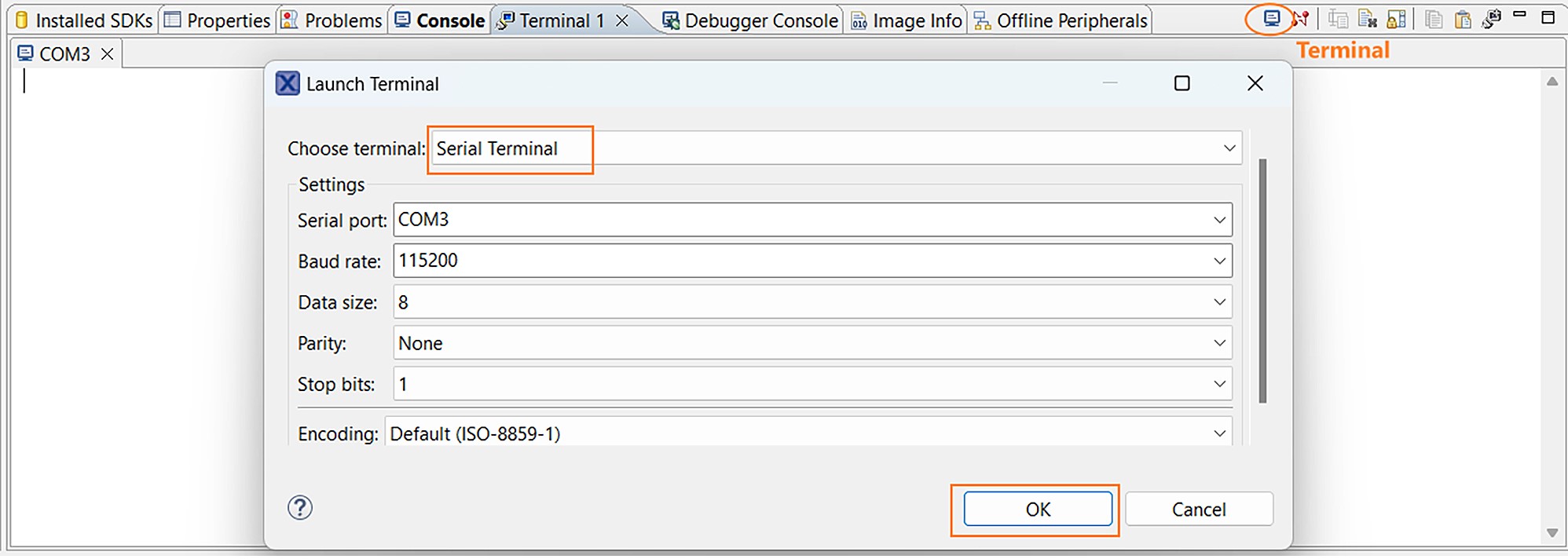
Execution and Monitoring
Open the serial terminal in MCUXpresso IDE for basic logging and prediction results display.
Summary
This guide outlines the configuration and deployment of the TSS AFCI application on MCXN547, enabling:
Real-time arc fault detection
Scalable multi-channel acquisition
Flexible deployment with library or binary models
The system is designed to support both development efficiency and production scalability.